Mechanical Autopen Simulation
Table of Contents
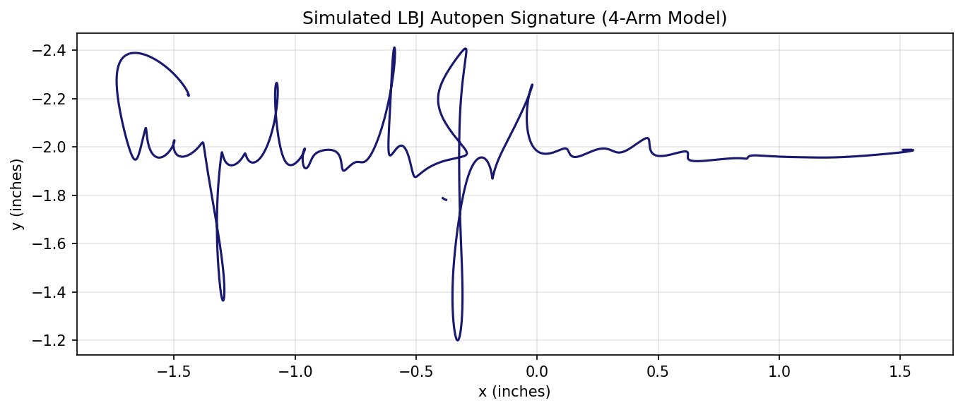
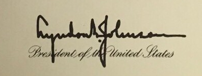
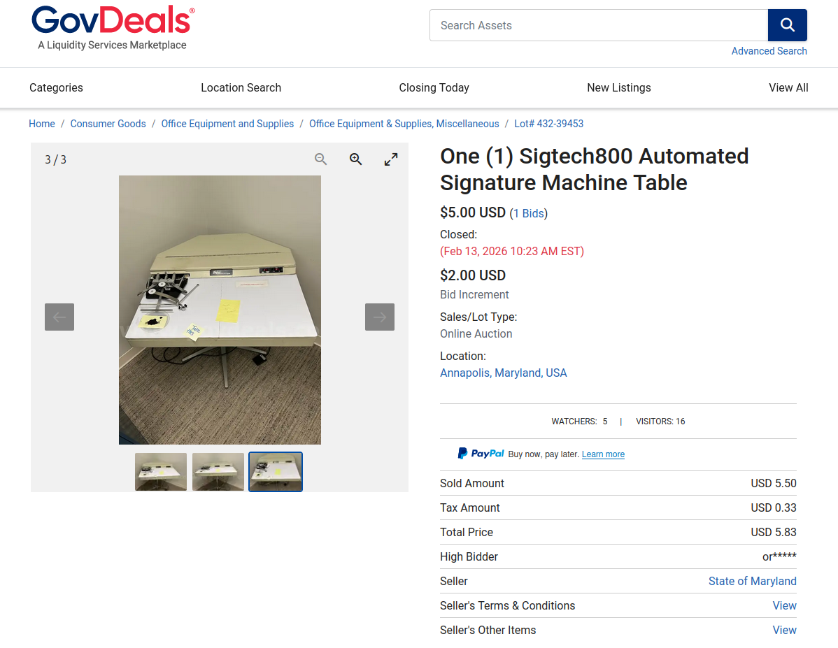
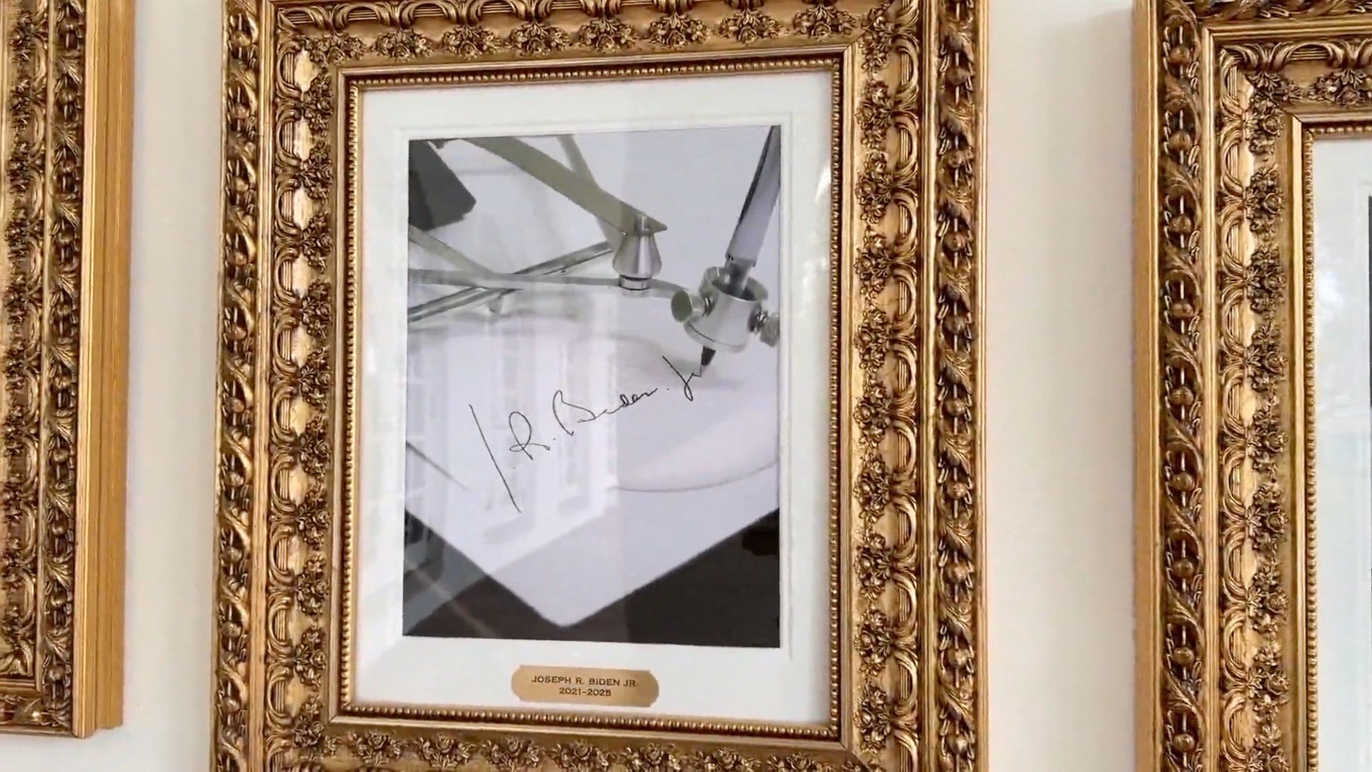
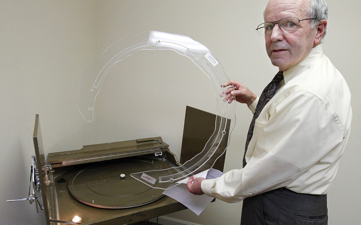
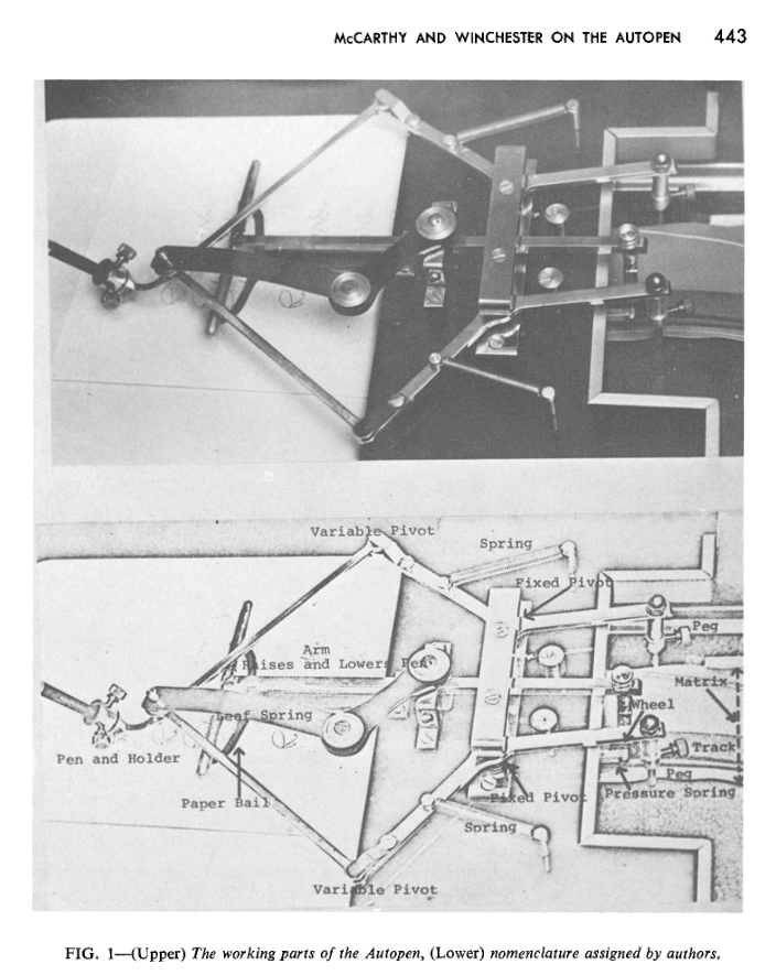
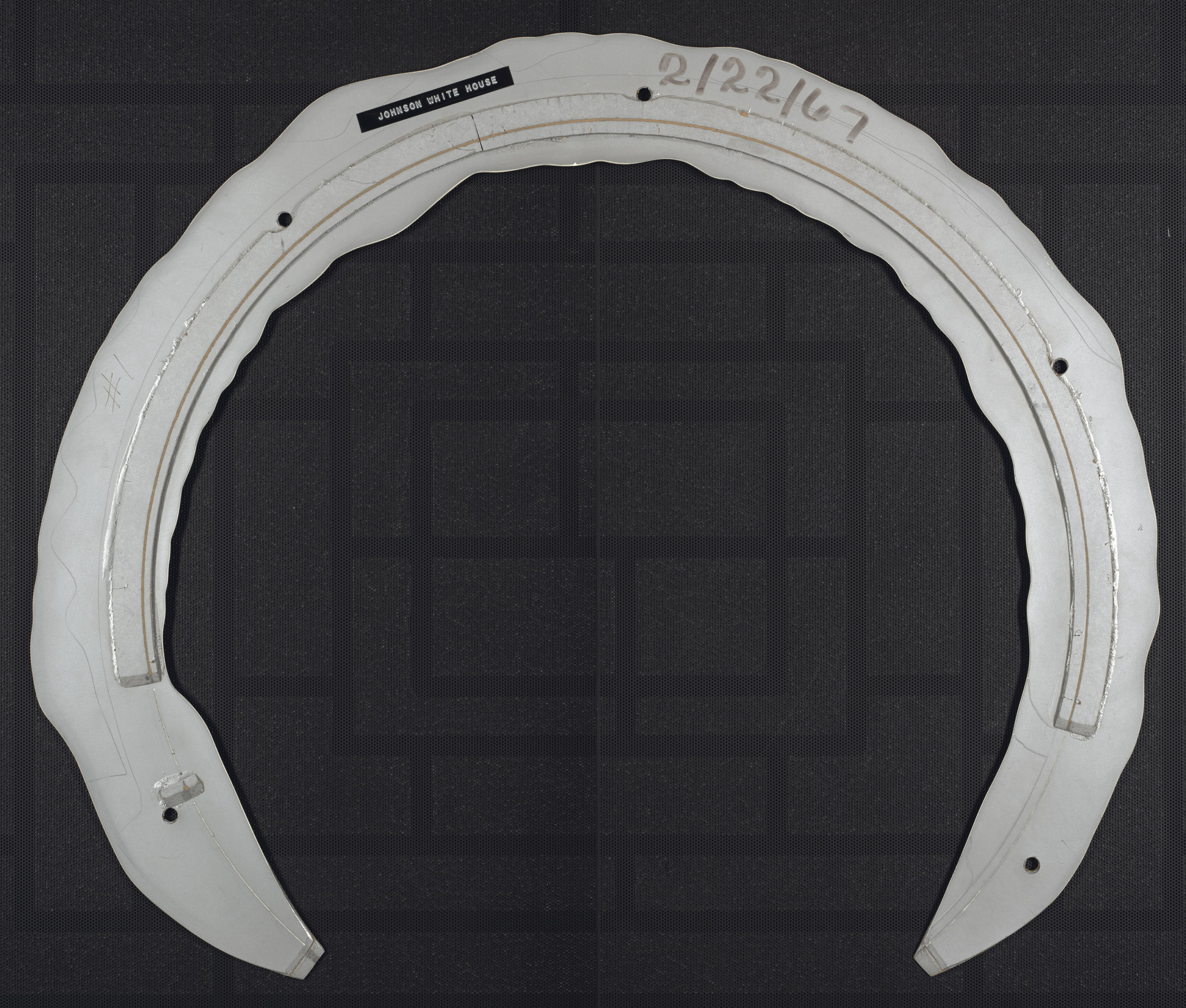
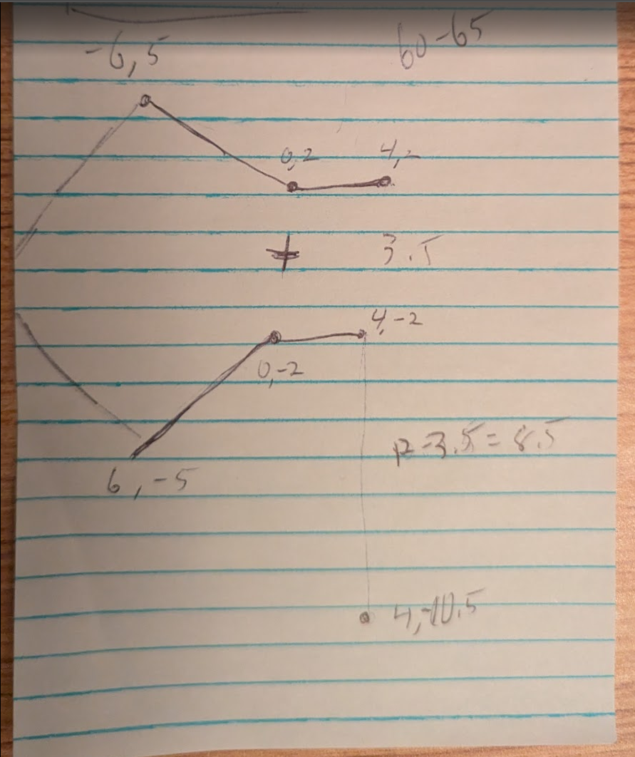
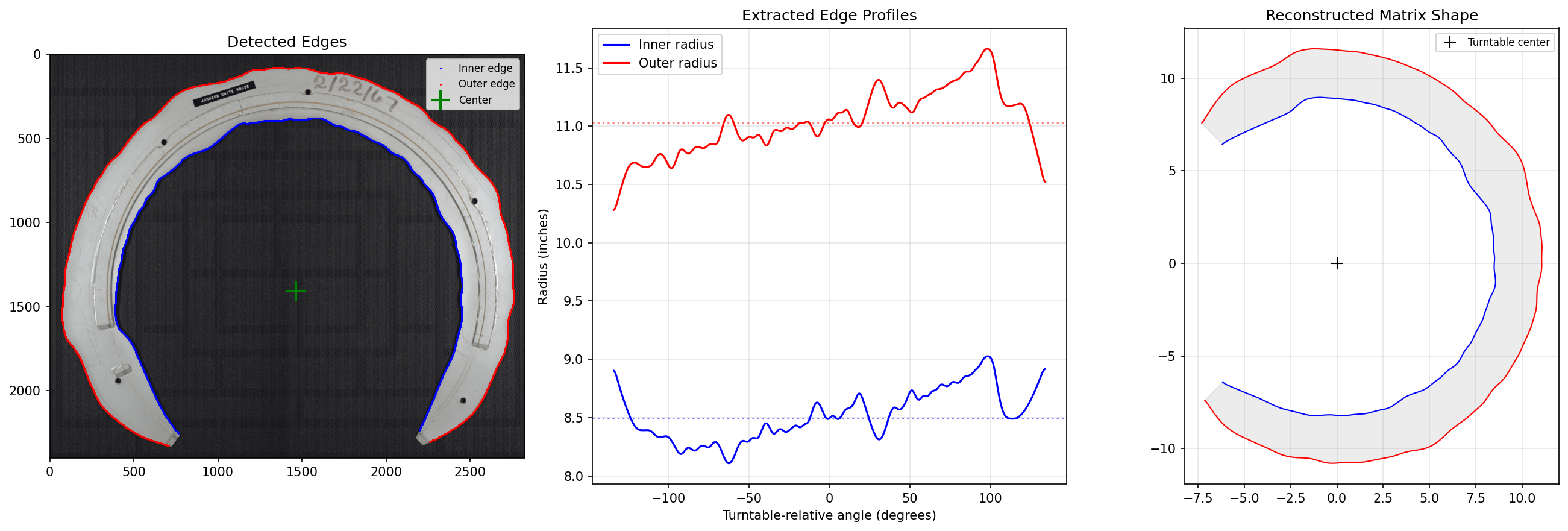
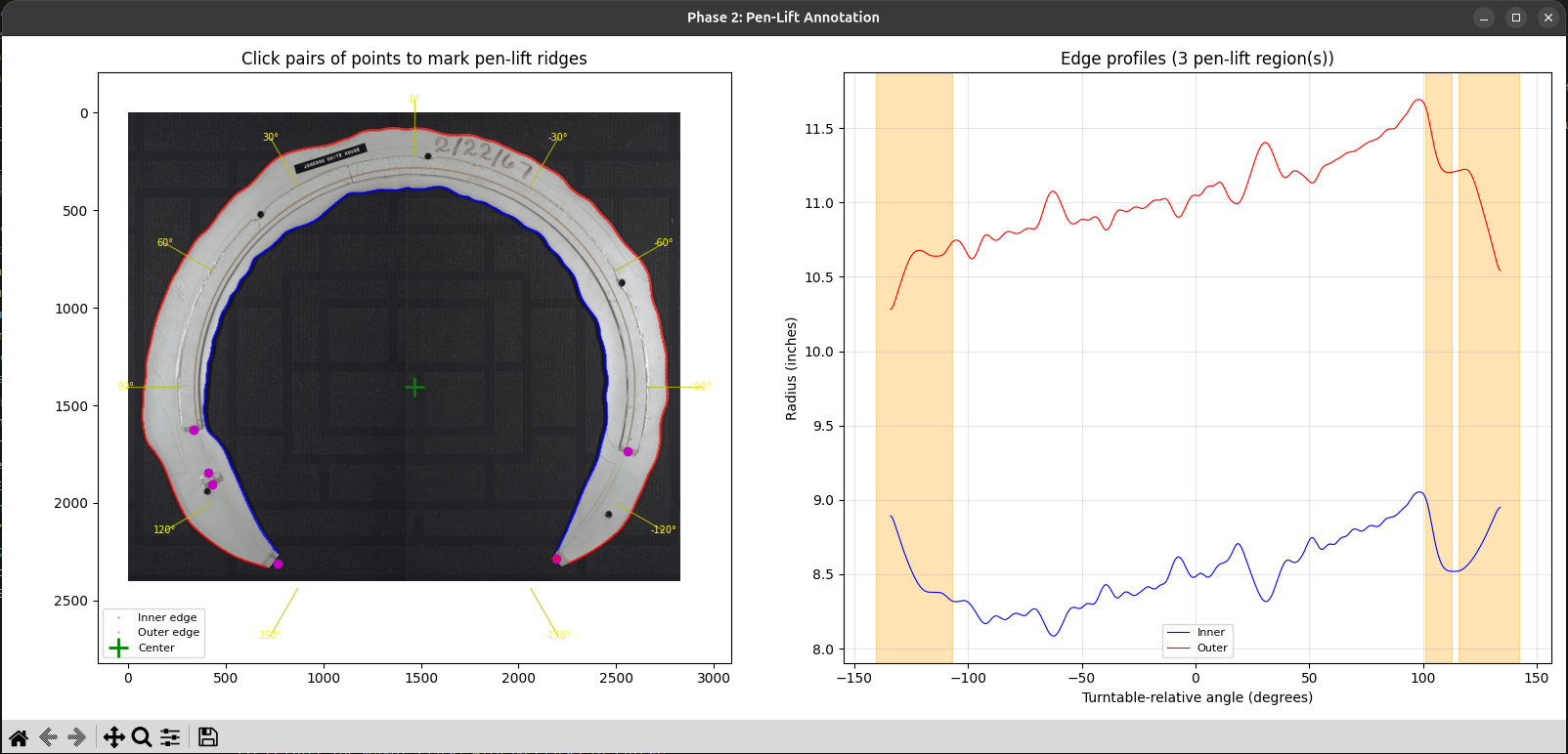
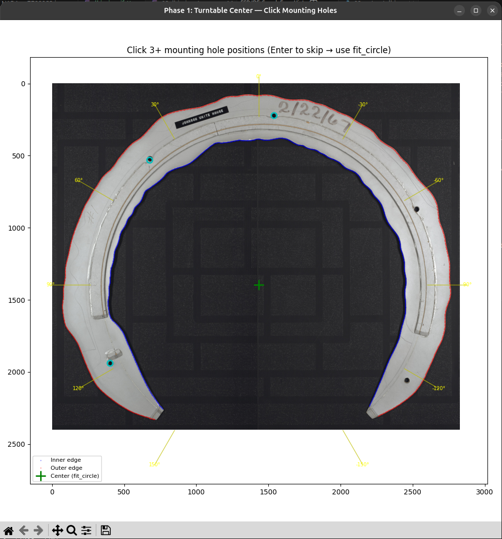
Reverse engineering Lyndon B. Johnson's signature by simulating a mechanical Autopen device using Python and computer vision. Or how I nerd sniped myself and ended up reverse engineering Lyndon B. Johnson’s signature The other evening I was killing time browsing a government surplus auction site. I had filtered it to relatively nearby auctions that were ending in the next 24 hours. Among the usual broken-down school buses and old computers, something caught my eye. A listing titled “One (1) Sigtech800 Automated Signature Machine Table”, even from the small picture on the search page it immediately drew my attention. The vintage metal mechanical mechanism taking up the left third of a fairly sizable desk was more than compelling, I am a sucker for vintage mechanical devices. When I first found the listing, there was only half an hour left in the auction and only a single bid of $5. It took a lot of willpower to not place a bid myself, but in the end my better judgment won out and I resisted buying this hulking machine I certainly don’t have the room for. My curiosity was, however, piqued, and I descended into what ended up being hours of researching, then simulating these old machines. I’ll start with a quick primer for anyone who hasn’t had the misfortune of becoming aware of what an Autopen is because of American politics. An Autopen is a device that can write out an individual’s signature. The general class of devices is referred to as “signing machines”, but much like Kleenex or Band-Aid, the Autopen brand name has become synonymous with the whole class. Signing machines do exactly what their name implies, they allow an individual to create a reusable representation of their signature, which can in the future be used in the signing machine to create a limitless amount of near-perfect examples of their signature on command. They have been used widely by politicians, famous individuals and others who need to sign a lot of paperwork since the 1950s. Modern Autopens are entirely computer controlled. They are essentially robotic devices that can take a digital representation of a signature and using electronic motors move a pen to render that signature onto a piece of paper. Their mechanical design does share some fairly obvious lineage with their pre-computer ancestors, however. These computer-controlled Autopens were first released into the market in the 1980s. The Autopen I came across, the Model 80, predates the computerized designs. These mechanical Autopens instead use a physical representation of the user’s signature. The Autopen company refers to them as a matrix or template. Each matrix stores a single signature and can be loaded in or out of the machine to allow multiple users for a machine and to allow a signature to be stored safely out of the way when it is not in authorized use. There seems to be very little written or recorded about these devices and how they work. At least that I could find searching the internet. The best resource I was able to find was the official website of Damilic, the company that owns the Autopen brand. Their site has a few short “Info” and “FAQ” pages that give a couple of paragraphs of explanation for some of the company’s history and legacy machines. Somewhere, in one of those pages was a link to the absolute best resource I was able to find through this whole project: a scanned PDF that Damilic had posted of a 1970s article from the Journal of Forensic Sciences. The article spans 7 pages and goes into a fair bit of detail on how the mechanical Autopens work, as well as having a labelled close-up shot of the primary mechanism of the machine. Just by staring at the mechanism, I could see how the two pins that ride along the matrix could provide the full two degrees of freedom needed for a signature. If both of the pin arms move in towards each other, the arms would swing outward and the pen would move towards the rest of the machine. Likewise, if the pins move outwards, the pen would be pushed away from the machine. Finally, if both pins move in the same direction, the pen would move in the opposite direction. None of these kinematics are simple though. Being built around the intersection of circles, there is a limit to how far my intuition could take me. So, while the article went a long way towards helping me understand the device, I wanted to find a way to build a deeper intuition for it. One other amazing resource I came across was a high-resolution picture of President Lyndon B. Johnson’s signature matrix from his time in office made available by the National Archives. Having gathered enough information to get a rough understanding of the device and then seeing the President Johnson matrix, I began to form an idea. I decided I’d like to try and digitally simulate one of these mechanical Autopens, so that I can play with it and watch it and try to build an intuition for how they work. And finally I wanted to see if I could reproduce President Johnson’s signature from the picture of his matrix. I did not have very high hopes I’d actually pull that second part off. I started by using the picture in the journal article to draw a sketch of the 4-bar linkage that makes up the heart of the machine and assign rough dimensions to all the pieces. I won’t be going into too much detail on the code for my simulations. I used Anthropic’s Claude Code to help with much of the development and in many ways don’t consider the code fully mine. It is not a codebase I would feel comfortable releasing under my name without a good amount of refactoring. With all that said, I would not have been able to get nearly as far in this work as quickly as I did without the use of Claude or a similar LLM coding tool. I will generally say that Claude was not very useful for the physical kinematics, but did much of the heavy lifting for the computer vision, UI creation, and general script boilerplate. I started by having Claude make a simple visualization of the 4-bar linkage interacting with a matrix. At first this was a random matrix that Claude had created that did not map to any actual signature. Having the visualization was critical for me, it was a very quick sanity check that the physics were being modeled correctly. Once the model seemed to be working for this random test template, I decided to move on to the President Johnson matrix. To simulate the matrix, I needed a tool that could be run on the source image and create an output file with the curve information required to run the simulation and visualization. There ended up being 3 main concerns to deal with: The image I was using is of quite high quality and the matrix has a high contrast against its background. This all makes the edge extraction a fairly simple computer vision task. Claude managed to get it mostly correct on its first try. If I am honest, once I confirmed that the edge extraction looked visually correct, I never dug too deep into what techniques it used to accomplish it. The shape of the top ridge of the matrix controls the downward pressure of the pen. As the ridge rises, it presses down the pen like a see-saw. Just looking at the source image, it was clear to me that it would be much harder to extract programmatically. For that reason, I didn’t bother to ask Claude to do it. Instead, I had it create a UI where I could click at each point the ridge starts or ends. The tool then extracts that alongside the curves of the matrix edges and saves it to a file for use in the simulation. As I iterated on the extraction and resulting simulation, it quickly became clear that having a precise center of rotation is critical for getting a good output. Originally I had Claude determine the center of the curves it extracted, and then I manually provided an offset from that in the form of an angle and magnitude. I even had Claude create a script to sweep a large set of angles and offset magnitudes, producing ~100 images. This managed to get a very reasonable output but seemed unacceptably brittle. Finally, while looking back at the images of the matrix and the Model 80, I noticed that there were 5 holes in the matrix that are seated into pegs on the turntable of the Autopen. From images of the Autopen device, it was clear that the turntable center was in the exact center of these pegs. With this insight I was able to have Claude add a step to the extraction script where I could click on 3+ peg holes on the matrix and it would use that to describe a circle and from that circle determine the center of rotation. With all three of those handled, this is what the output looks like visualized. In actuality it is all stored in a binary file that can be passed to the simulator or visualizer. You can see in green the pen up and down movement. It is clear to see that the red and blue traces of the matrix have a global shift over the course of the matrix relative to its center. This is what encodes the left-to-right movement of the signature being written out. The global shift moves the pen left to right while the local variations are encoding the movement for each character of the signature. You can also make out at the very end where the curves move sharply while the pen is lifted only to drop back down momentarily for the “.” of the “B”. In the end, I was very pleased with the results I got from the President Johnson matrix image. Below you can see a side-by-side of my results and listing image for an eBay listing for an Autopen LBJ signature. The issue that stands out the most to me is the misplacement of the “.” after the “B”. From my prior experimentation, I know this can be resolved by manually shifting the center of rotation of the matrix just slightly. If I had to guess, it is a consequence of the source being a real picture from a camera and therefore not being a perfectly orthographic projection, which is an implicit assumption of the extraction tool. The image could also be slightly off of perfectly flat relative to the matrix. If I find some more motivation or this generates significant interest, there are some next steps I’d like to take in this vein of work. I’d love to recreate the simulator in TypeScript and create a website that allows a visitor to use a touch input or mouse to create a signature and then have them be created as a virtual matrix. That virtual matrix along with the LBJ matrix and maybe any other famous matrices I manage to find could then be simulated and visualized. Finally, I’d really love to be able to have the site export those templates as STL or DXF files to be 3D printed or laser cut (presumably at a smaller scale than the 2 ft across of the originals). I could then design a 3D printable Autopen type device. All of these feel very doable but would also require quite a bit of time investment. It would make a very interesting conversation piece and engineering demonstration though. It would kill it at a science or engineering museum.The Inspiration
Background & Research
The Simulation
LLM Coding Adventures
Computer Vision Detour
Matrix Edges
Pen Lift
Center of Rotation
Extraction Results
Results