Bluetooth Manometer for Carburetor Synchronization
Bottom Line Up Front
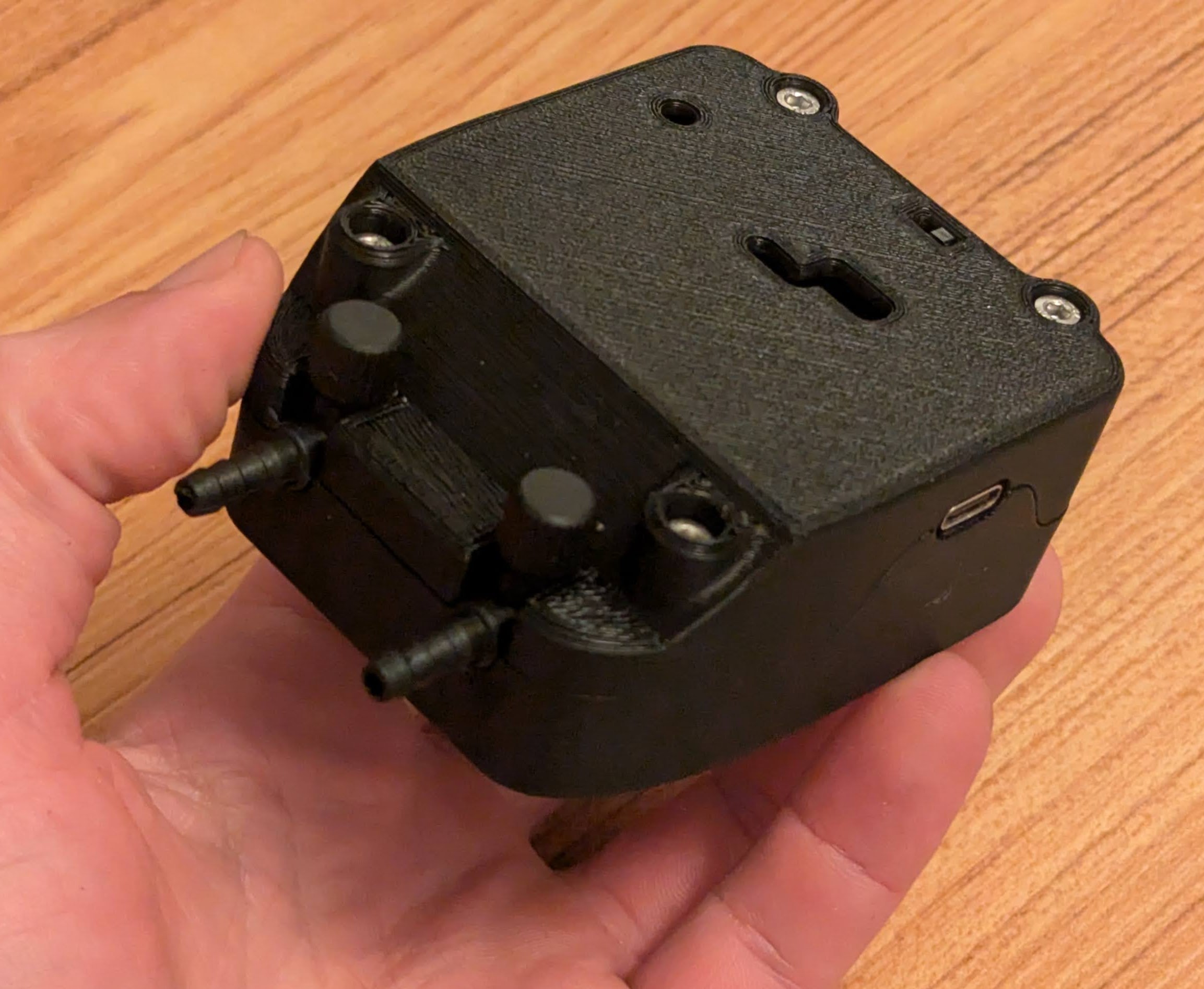
In this project, I work towards creating a portable device for synchronizing carburetors that uses bluetooth to stream live vacuum pressure readings to a phone or laptop. Pressure readings are presented as a time series plot making it easier to see how adjustments are affecting the readings. Below are some photos of the device and screenshots of the UI as I used it to synchronize the carbs on my Honda.
 |
|---|
| The device as it exists right now |
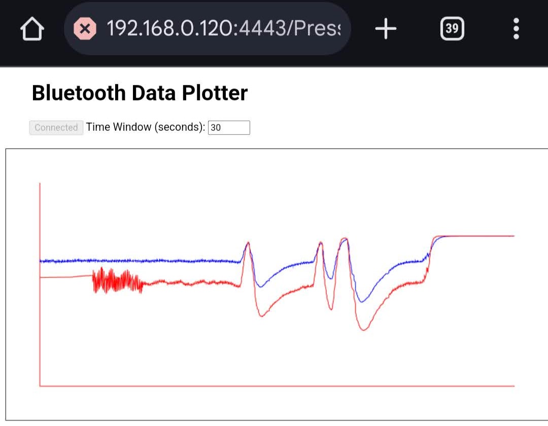 |
| The prototype UI |
Electrical Components Design
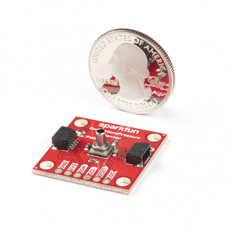
The key enabler of this design is a Honeywell 0-25 PSI digital absolute pressure sensor. Specifically, for the prototype I am using the SparkFun Qwiic MicroPressure which provides an economical and convenient breakout board for the sensor. This sensor provides accurate readings across the entire pressure range we are interested in and is easy to interface over I2C. For this prototype, I am using two of the sensors since I personally own a two cylinder motorcycle; however, scaling up the design to 4 or even 6 sensors would not be difficult.
 |
|---|
| SparkFun Qwiic MicroPressure Device. Image from SparkFun and licensed CC BY 2.0 |
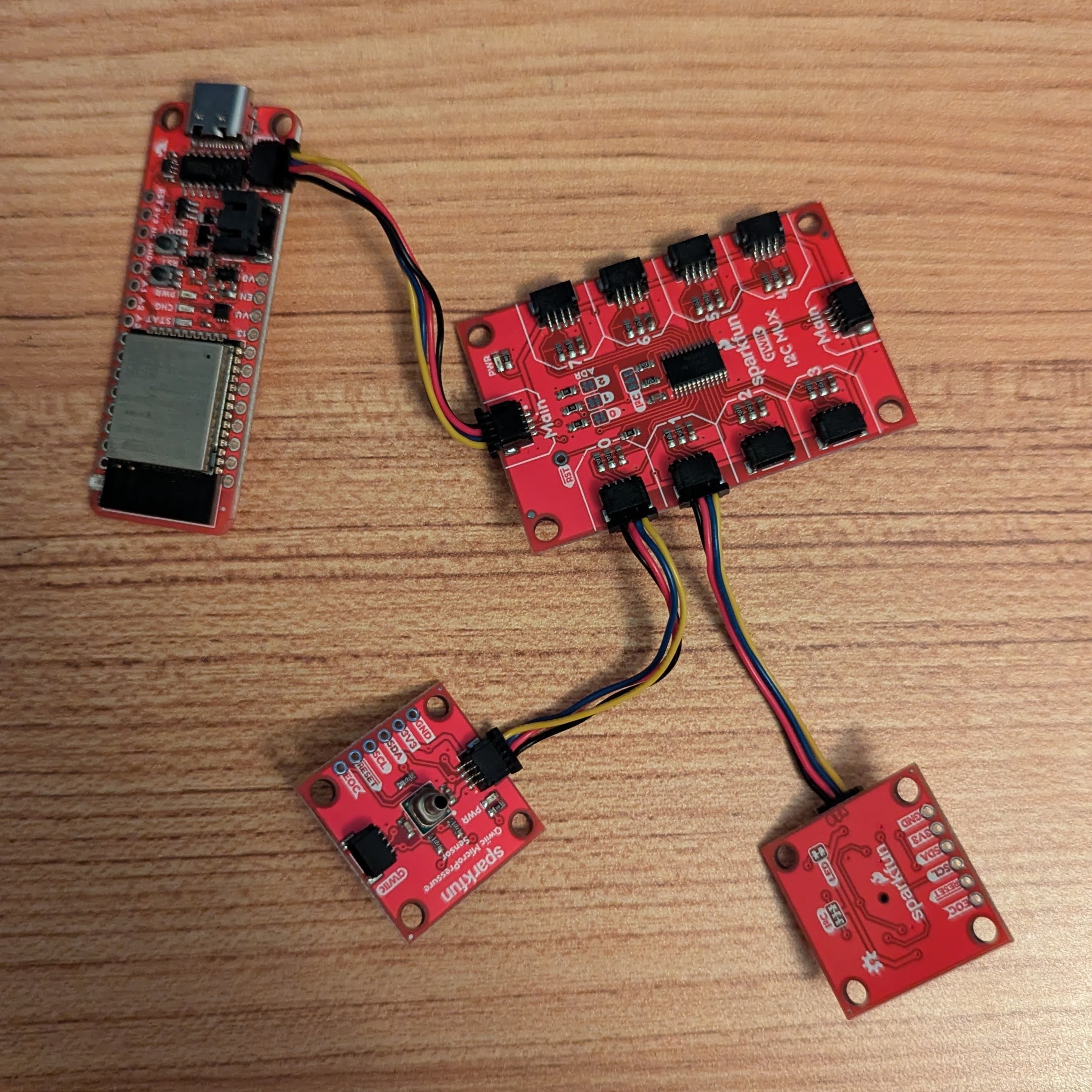
Reading the sensors and serving Bluetooth Low Energy communications is handled by the SparkFun ESP32 WROOM Thing Plus with USB-C which uses the Espressif ESP32 microcontroller. This was my first time using this development board and I was extremely impressed. The board’s battery management and power system is very well designed and by staying in the SparkFun product ecosystem connecting the pressure sensors using their Qwiic system was painless.
Finally, rounding out the electrical components is a LiPo battery, a small switch for turning on and off the device, and a I2C Mux board. I used the mux board to allow using two sensors from the one Qwiic connector on the Thing Plus board. As provided by Sparkfun, the sensors all share the same I2C address which would clash if they shared the same I2C bus. Honeywell provides the sensor with up to 8 different I2C addresses, but each must be ordered as a separate model of the device. For this reason it is very reasonable the SparkFun only provides the one model, however in the future a larger production run of this device would be able to simplify the design by using separate models of the sensor.
 |
|---|
| The electrical components less the battery connected together |
Firmware
The firmware was written using the Arduino IDE, mainly for ease of development. SparkFun provides examples and libraries for most of their components in the Arduino ecosystem. The firmware sets up a Bluetooth Low Energy Service and offers two characteristics; one for each of the sensors. Each characteristic advertises a single 32 bit float value. When a client connects the device it begins sampling the sensors and publishing their values in a loop with a 10 Millisecond delay at the end of each iteration.
The code can be seen here on github
Web UI
To display the data, I decided the path of least resistance would to use the Bluetooth Web Standards. This approach ended up working really well and was very easy to develop; however, the Bluetooth web standard is not particularly well supported so it will only run on certain combinations of browsers and devices. I found Chrome on my Android phone to work very well.
The actual data is plotted using calls to the Canvas API (which has great browser support), this makes the page highly performant and means it has no external dependencies. The HTML and Javascript all fit in one file comfortably. The code is available here but I will warn I have almost no experience with Javascript and heavily leaned on ChatGPT to write this page so don’t judge it too harshly.
Physical Design
Finally, I designed a 3D printable case that holds everything. By chance some flow regulator valve’s I already had that were designed for 4mm ID tubing happen to slide over the sensor’s port with a nice tight fit. The pressure sensors are somewhat fragile especially with the extra leverage of the valve adapters when they are attached (I already managed to break one of them). So, when designing the case I took extra care to ensure that the valve body and sensors were both held securely. Especially since the other half of the valve body extends from the case and is the primary touch point of the device in use.
Here are some images of my CAD design:
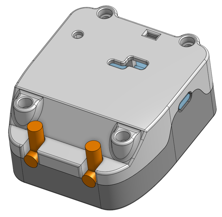 |
|---|
| The overall appearance of the device as designed |
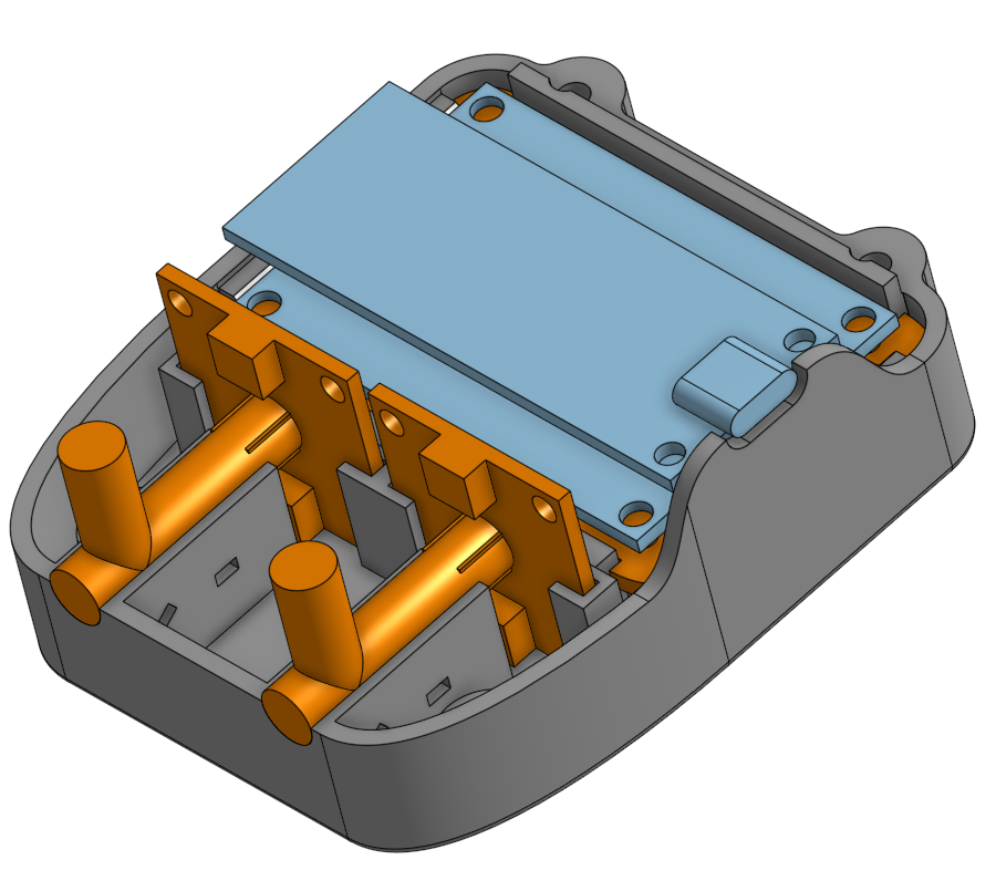 |
| The device with the top of the case removed |
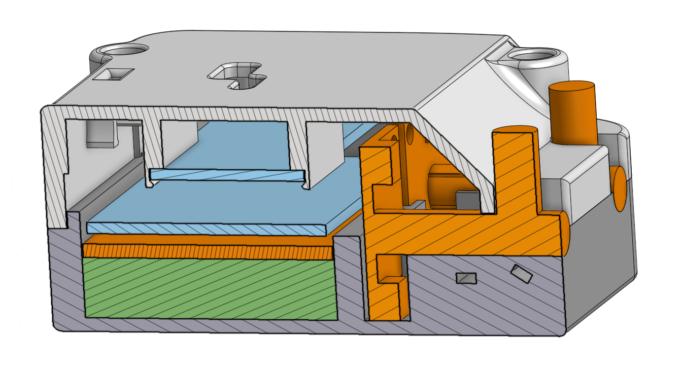 |
| A cross section view of the case design |
Looking at the cross-section view:
- The green part is a placeholder for the battery
- The top light blue part is the microcontroller
- The bottom light blue part is the I2C mux
- The orange part between the battery and I2C mux is a 3d printed piece that snaps into place securing the battery and mux
- The two sensors are also in orange. Note that the regulator valves I am using were modeled in as if they were both one part
In the bottom shell of the case there are rectangular holes in the geometry that supports the regulator valves. They are used to securely zip tie the valves into place. The power switch snaps into place in the top shell of the case, the geometry for this can just barely be made out in the top shell of the case in the cross-section view. The two halves of the case are held together with four M3 screws. The bottom shell has hexagonal holes that are a friction fit for the nuts that the screws thread into.
Here are a few images of the device while being assembled and from various angles:
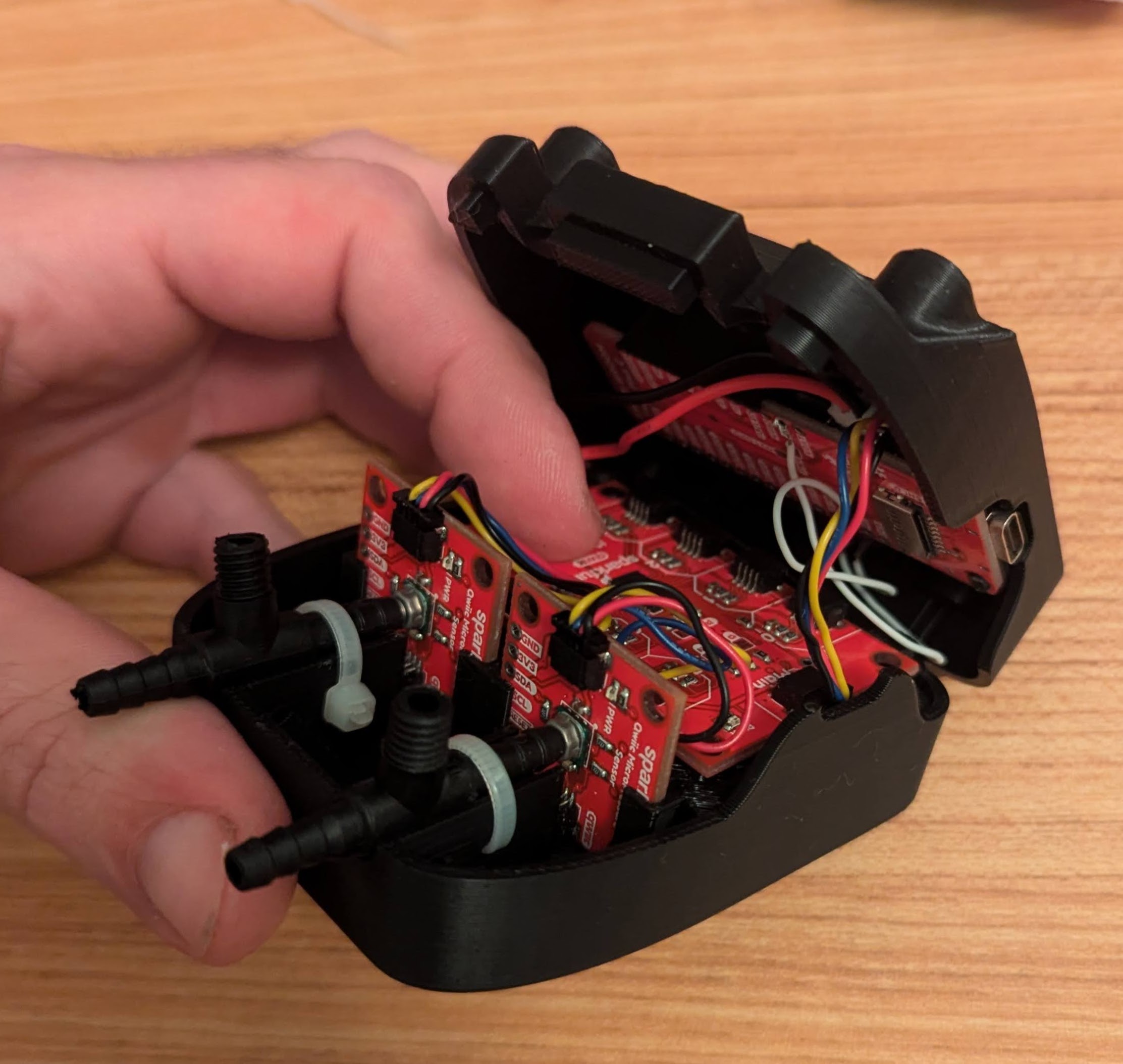 |
|---|
| The device with the top of the case removed |
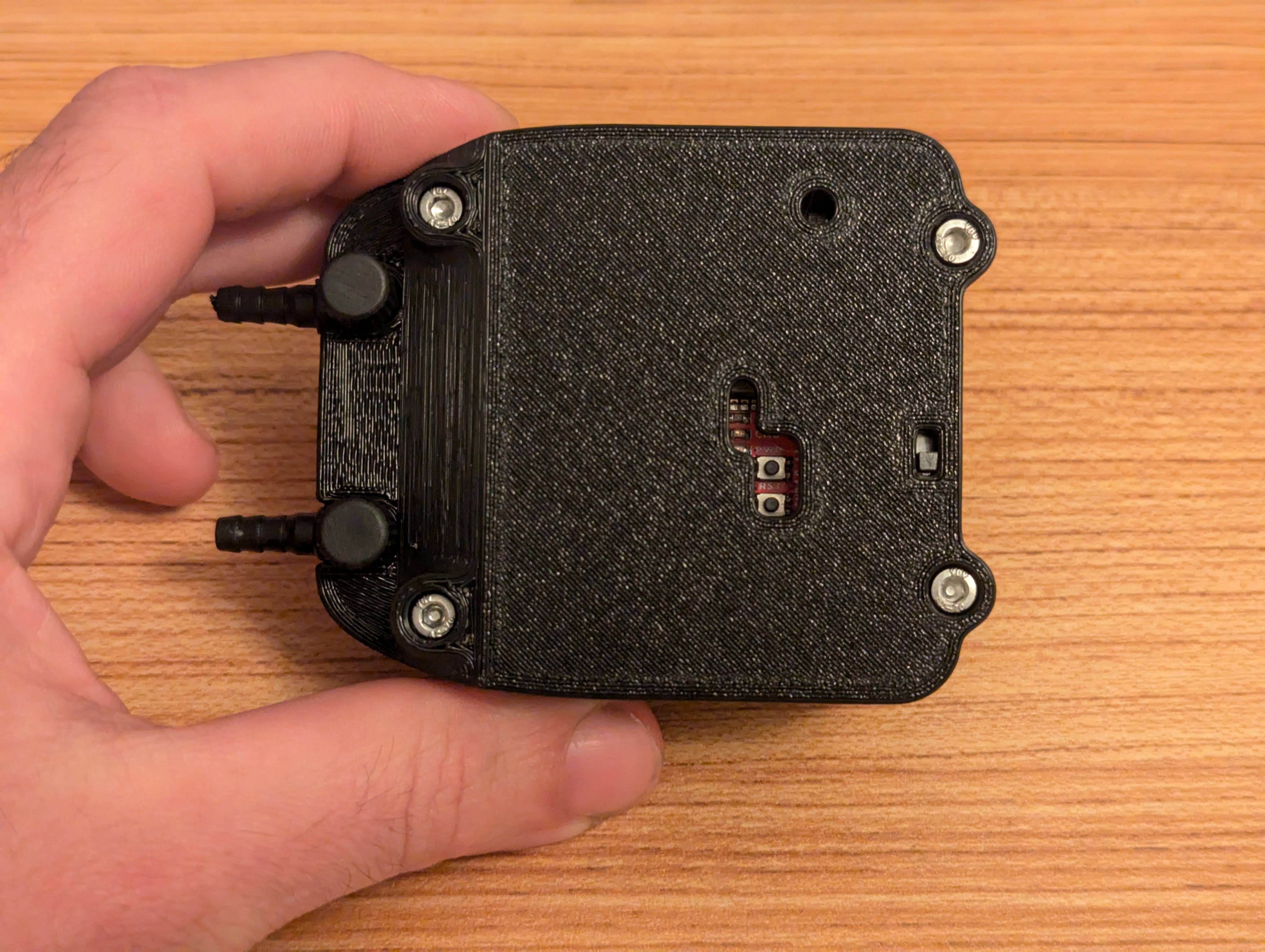 |
| Top down view of the device |
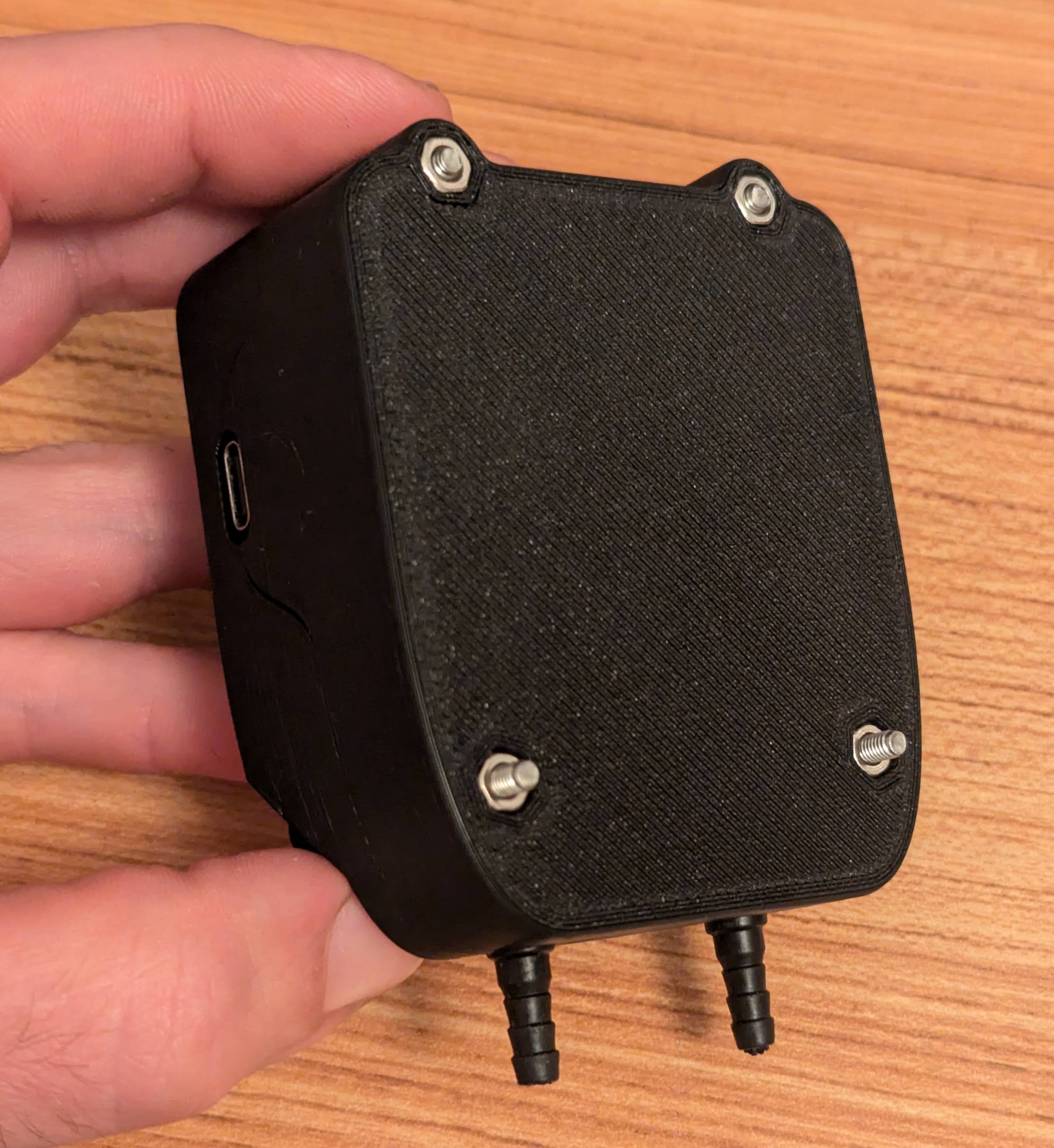 |
| Underside view of the device |
And finally for fun here are a few printed iterations of the design as I worked through the design process:
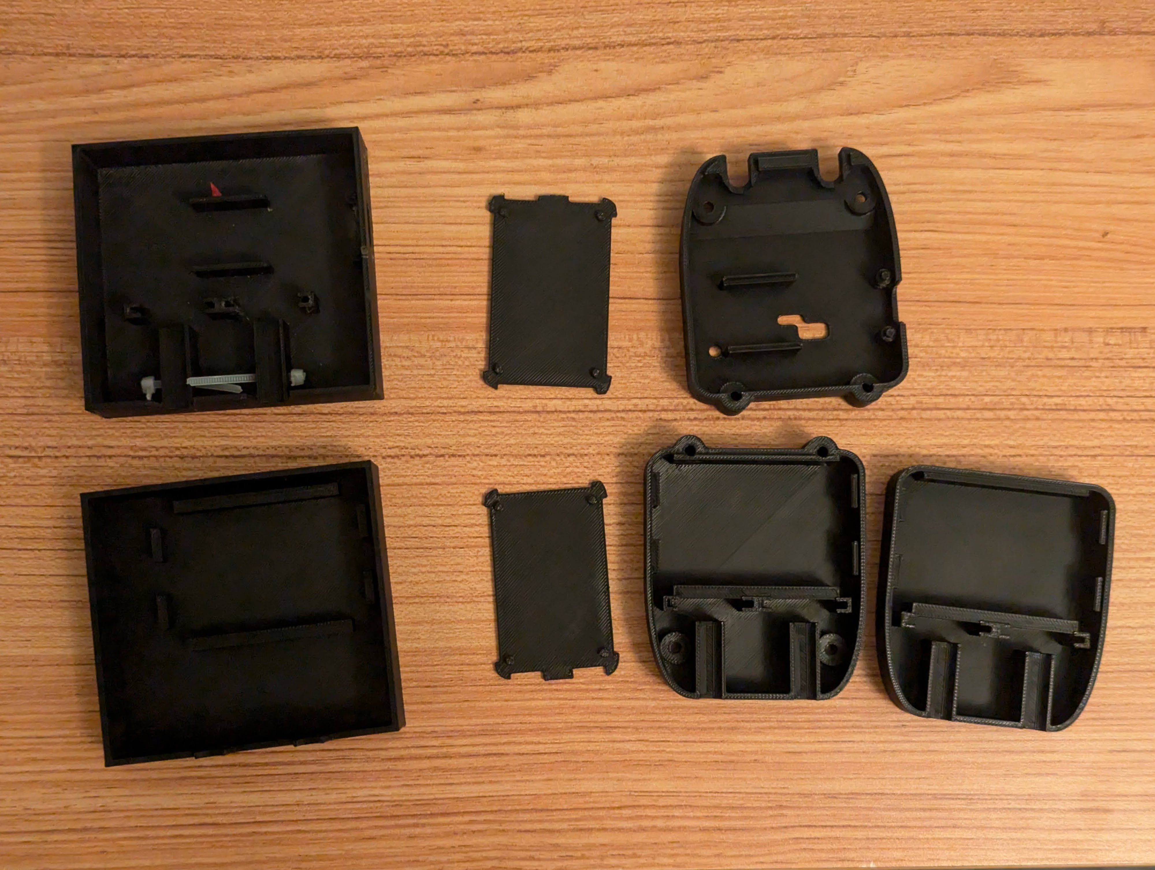 |
|---|
| Iterations of the case design |
Hosted UI
If you end up building one of these you can access the UI Page here on my website by scanning the QR code below of going to the URL https://scatena.co/pressure_sense

Next Steps
With the work described above I have a device that works for me and my use case. In fact it has already helped me get my motorcycle running better. Hopefully, the information above is also enough that anyone else who is interested could make their own. However, if it seems like their is potential interest I have been batting around the idea of spending more time on the project to really elevate it from a one-off prototype to at least an Alpha product, maybe even trying to sell kits or PCBs on my site or a crowd funding site. If I went that direction the below is a minimum of the additional work I would want to do before launching.
- A custom PCB, to cut down on costs, reduce part count, and improve packaging
- A case design that integrates a pressure manifold for the sensors and avoids the need for the flow regulator valves
- Improved firmware to add battery information to BLE outputs and possibly uses power saving modes when the device it idle
- Improved UI, that is easier to use and looks better. I will also probably have to reevaluate whether the Web Bluetooth standard is the right tool for the job. I love how light weight and easy to use it is, but I don’t love that it forces users to have a web connection just to interact with a simple application, and the lack of support on iOS and Linux devices is less than ideal